Preparing jobs for the Powder Printer
Export your model as a mesh from the modeler of your choice. Although nearly any mesh filetype will work, we recommend using the STL filetype. To minimize unintended abberations in your finished model, you should export closed, solid geometry that has been appropriately checked for mesh integrity using this tutorial.
Opening your model
Open the program 3DPrint on a School of Architecture workstation. it should be available on all studio computers, lab machines, and virtual workstations.

When the software first opens, it will prompt you to open a model.

After loading the model, 3DPrint will ask for the scale of the object, based on the size of the mesh. 3DPrint will select by the default the unit that makes your object as large as possible, while still fitting into the build volume in its initial orientation. You can select any of the four units at this point, and the dimensions will be
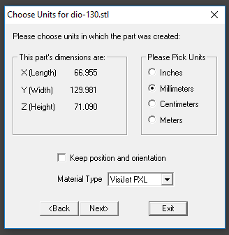
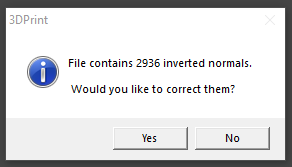
The program may prompt you when you first load a model that it will attempt to apply various fixes to it. You should let 3DPrint attempt to fix your model if it detects issues with it, but be sure to check closely that it doesn’t make any unexpected changes to your model that might produce an undesirable final part from the printer. These fixes may include correcting the normals of your mesh faces, closing gaps, or other things. Being sure to check your mesh for these issues in your modeler will prevent these problems from appearing and minimizing their impact.
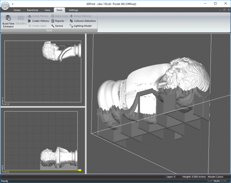
After your object is loaded, the full interface will appear. You are shown a three-pane window. The top left shows a plan of the build volume, the bottom left shows an elevation, and the right pane is an isometric view of the build volume. Five tabs appear at the top of the window, with a ribbon that will populate with different functions depending on the tab.

The iso view can be rotated by left-clicking and dragging. Left-clicking and dragging the model in either of the left panes will grab your object and move them around in their corresponding planes. Keep in mind on the elevation, that your models can be floated in mid-air. This is fine! However, it’s typically very inefficient. Printing time corresponds directly to the highest point in your print. Raising your objects off the build bed can sometimes help preserve sharp points on objects that must point down, but otherwise it only extends the time to finish your print.
If your object has an orange bounding box around it when selected, that means that the model is within the bounds of the print bed. If the bounding box around your object is red, then the model is outside the bounds of the print bed and should be moved or reoriented such that is within the print bed’s volume.
Transform controls
![]()
To adjust the position of your model precisely, first click on your model in one of the three panes, then click on the Transform tab at the top of the window. Click on a field next to the X, Y, or Z in the Translate section, then enter the value to move the selected model. By default, the units being used here will be inches, regardless of what units your model was imported in. When you’ve set the values where you want, hit the Move button, next to the 4-way arrow.
Rotating your object works similarly, where you can rotate your model about any of the three cartesian axes, then hit the Rotate button. Scaling works somewhat differently, as it will always happen uniformly in all three axes at once. Changing any value, will immediately scale your object to fit the value in that dimension, and the others to the same proportion. If you want to scale by a specific percentage, set that percentage in the Scale section, then hit the Scale button above it.
The functions in the Justify section will align your model to the build volume itself. Bottom will move your object, in its current orientation, to the bottom of the print volume. Clicking on the arrow to the right of the Left/Right and Front/Back dropdown menus will give you the option to move your model against the outer edges of the print volume or center it. The functions in the Mirror section work as one would expect.
Viewing your slices
The View tab allows you to set the right pane of the window to any of the four options available in the View section on the left side of the ribbon. The Display section can allow you to examine the individual printed layers of your model by enabling the 2D View mode. Do this by clicking on the Toggle 2D View button. What will be shown is the view below.

The yellow line on the bottom left pane’s model represents a plan-cut of each layer (shown in the right pane) that will be printed. It can be left-click and dragged up and down to show different layers, or a specific layer can be selected in the Layer section. The buttons to either side of the numeric layer field will move the slice up or down by either 1 or 10 layers at a time. This view can be very useful in diagnosing small problems with your model that may otherwise, not be visible. Holes will sometimes appear in the 2D view that indicate places where printer will not lay down binder on the powder. Tiny gaps that don’t stack from layer to layer, will not effect the finished part, but gaps that stack repeatedly can lead to holes in the finished part.
Useful tools
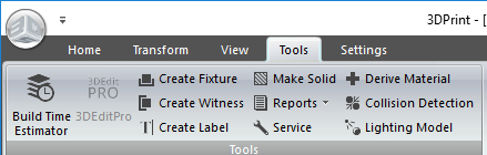
The left most button on the Tools tab is the Build Time Estimator. Clicking on it will show you a window with statistics about your print job as it is currently oriented and sized.

The three highlighted lines shown above contain the print time and consumables that will be used by your print. Note that the print time estimate does not include the post-print curing time, which can be up to 2 additional hours, or the part removal time, which for especially delicate models can take up to another hour. You can find your part’s price with the following equation:
(Binder volume in mL) × ($0.28/mL) + (Powder volume in inches3) × ($1.97/in3) = (Total part price)
Although the time estimate has some variance to it, the part cost will not change if your model does not change. Keep in mind that a part that does not change in size, but does change in orientation or location in the build bed can sometimes change very slightly in price, usually by less than 0.5% of the total cost, if at all.
If you load multiple objects into a single print bed, you may want to look for collisions between close, but separate objects that should remain separate after printing. You can do this automatically with the Collision Detection tool.
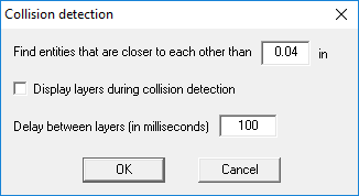
This tool will find objects that overlap with each other and others that, while not necessarily overlapping, are close enough to potentially fuse during printing. If you want to look for potential collisions larger than that, you can adjust the top field in the Collision Detection window. Checking the Display layers… checkbox will show you the layer interface while the software looks for these issues. Setting the delay to a larger value will increase the accuracy of the detection process, though it will take longer to run the process.
If your object is likely to collapse under its own weight during powder removal, you can have 3DPrint automatically generate a support structure called a “fixture” with the Create Fixture function. Click on the Create Fixture button, and, unless you think you will need additional support, use the default settings.
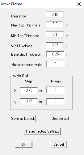
When you click on the OK button, an offset shell with a supporting grid will be generated under your model. This will help support any delicate geometry while your part is removed from the printer. Be sure to re-run your build estimation because you will need to pay for the model materials consumed when printing a fixture with your model.
Saving and submitting a print file
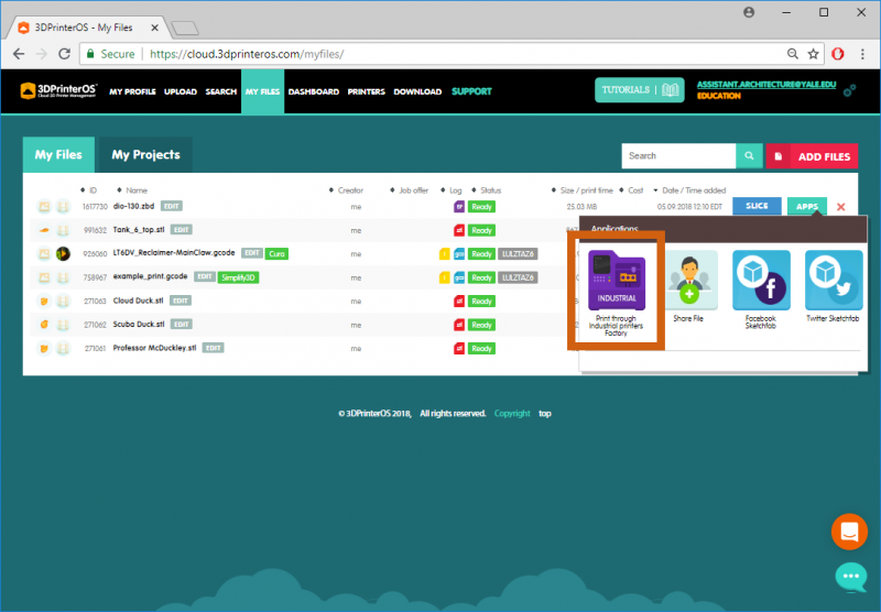
When your part has been appropriately arranged, scaled, and checked over, save your print bed to be submitted for printing. From the Home tab, click on the Save or Save As buttons. Save out a ZBD file, then upload this file to 3dPrinterOS. From your My Files page on 3dPrinterOS click on the Add Files button.

Click and drag your ZBD file into the window that comes up or browse for your file to upload it.

After your files uploads, click on the Save and go to My Files button, then click on the Apps button after the page reloads and the file is scanned. In the next window, click on the Print through Industrial Printers Factory button. Remember, only submit
In the Select A Printer window that then appears, click on the Queue button to the right of the Powder Printer.

At this point, your print will be sent to the powder printer queue, checked over for any issues, and sent to the powder printer when its next available. When your part has finished printing it will be removed by DM staff and placed on the 5th floor printing cluster shelves to be picked up. Please pick up your parts as soon as possible, as parts left unattended for more than four days may be discarded, especially during midterms and finals when shelf space is limited.
Please note, the DM office reserves the right to reorient or change the location in the bed of any part you submit without first consulting you, but this will only be to avoid potential problems. We also reserve the right to combine your part with other prints to increase throughput, but if this will significantly impact delivery time for the part, we will warn you of this happening first. Typically, this is only done overnight or over weekends when the machine will not be serviced by DM staff to minimize downtime, and should not normally impact delivery time on a part in a practical way. DM staff may also cancel your print if there are issues that cannot be addressed without changing the model. You will be emailed about this cancellation if this occurs. If your print is canceled, your place in the queue is forfeited and any newly submitted models will be placed in the queue when they are uploaded.